Tag Archives: arduino

Pico Power

An active Atmega328 consumes over 10mA of current at around 5V. To reduce power consumption various techniques can be used. Using all the techniques below I was able to reduce power consumption to less than 0.001 mA (my multimeter reads 0.000mA).

Turn off ADC
Set ADEN bit to 1 in register ADCSRA:

ADCSRA &= ~(_BV(ADEN));

Turn off Analog Comparator
Set ACD bit to 1 in ACSR

ACSR &= ~(_BV(ACD));

Turn off the Watchdog Timer
Straightforward but first remember to unset the flags which are set on Reset.

#include <avr/wdt.h>

MCUSR = 0;
wdt_disable();

Turn off power to peripherals
Set bits in the PRR (Power Reduction Register)

PRR = 0b11001111;
Bit Label Purpose
 7  PRTWI  Shut down TWI by writing 1.
 6  PRTIM2  Shut down Timer/Counter2 in synch mode (AS2 = 0).
 5  PRTIM0  Shut down Timer/Counter0 by writing 1.
 4  Reserved (set to 0).
 3  PRTIM1  Shut down Timer/Counter1.
 2  PRSPI  Shut down SPI by writing 1.
 1  PRUSART0  Shut down USART by writing 1.
 0  PRADC  Shut down ADC. ADC must be disabled before shut down.

Sleep whenever possible
Setup the chip in a particular mode. Can be done in setup.

set_sleep_mode(SLEEP_MODE_PWR_DOWN);
Sleep Mode Meaning
 SLEEP_MODE_IDLE  Turn off CPU clock
 SLEEP_MODE_ADC  ADC Noise Reduction. Turn of I/O clock in addition.
 SLEEP_MODE_PWR_DOWN  Power Down. All clocks off. Cannot wake up from timer
 SLEEP_MODE_PWR_SAVE  Allows Timer2 to be running. Power Down + Timer.
#include <avr/sleep.h>
set_sleep_mode(SLEEP_MODE_PWR_DOWN); // Setup Power mode

cli();  // Disable interrupts
// Do whatever if needed to confirm we need to go to sleep
sleep_enable(); // Enable sleep (needed to prevent us going to sleep by accident)
sleep_bod_disable();  // Optionally disable the BOD
sei();  // Enable interrupts just before going to sleep
sleep_cpu();  // Go to sleep
sleep_disable(); // When woken up - disable sleep to be on the safe side

Disable BOD when sleeping
This should have been really simple but it’s unnecessarily complex (it seems to me) requiring first setting and then unsetting a bit. The below function may be used (as in example above).

#define sleep_bod_disable() \
{ \
uint8_t tempreg; \
__asm__ __volatile__("in %[tempreg], %[mcucr]" "\n\t" \
"ori %[tempreg], %[bods_bodse]" "\n\t" \
"out %[mcucr], %[tempreg]" "\n\t" \
"andi %[tempreg], %[not_bodse]" "\n\t" \
"out %[mcucr], %[tempreg]" \
: [tempreg] "=&d" (tempreg) \
: [mcucr] "I" _SFR_IO_ADDR(MCUCR), \
[bods_bodse] "i" (_BV(BODS) | _BV(BODSE)), \
[not_bodse] "i" (~_BV(BODSE))); \
}
Arduino interrupts beyond Pins 2 & 3

Pins 2 & 3 on the Arduino are great to attach interrupts to; to pick up input even when the Arduino is asleep. The AVR chip though provides 3 more interrupt vectors that can be used to catch interrupts on all pins – even the crystal pins.

These interrupts though are change interrupts and so requires a clock to be present. Therefore, will not be suitable to wake up the Arduino from deep sleep.

Below is example code where interrupts are configured on Pin 8 & Pin 9.

See the Basic AVR page for details on the registers used.

volatile boolean pin8or9changedState = false;

ISR(PCINT0_vect) {
  pin8or9changedState = true;
}

void setup()
{
  Serial.begin(9600);
  Serial.println("Ready...");

  // Enable pull-up on Pin 8 (PB0) & Pin 9 (PB1)
  PORTB |= _BV(PORTB0) | _BV(PORTB1);

  // Enable interrupt on Pin 8 (PCINT0) & Pin 9 (PCINT1)
  PCICR |= _BV(PCIE0);
  PCMSK0 |= _BV(PCINT0) | _BV(PCINT1);
}

void loop()
{
  if (pin8or9changedState) {
    Serial.println("Pin 8 or 9 changed state...");
    pin8or9changedState = false;
  }
}

Timer Basics

The ATMega328 has 3 timers that can used in various ways including keeping time, triggering interrupts, PWM etc. Arduino uses up TIMER0 for functions such as millis, micros etc.

TIMER1 and TIMER2 are available. Below is a contrived example of building a custom timer based on TIMER2. The code is designed to run on a processor clocked at 16MHz and prints out some text at 1Hz. A prescaler of 1024 is combined with a counter to 251. This gives a counter up to: 16e6/(1024*251) = 62.25. Counting up to 62 gives a time very close to 1 sec.

See the Basic AVR page for details on the registers used.

volatile uint32_t counter = 0;

// Interrupt based on Compare Match A vector
ISR(TIMER2_COMPA_vect) {
  counter++;
}

long ms = 0;

void setup() {
  Serial.begin(9600);
  Serial.println("Ready...");

  // Reset, then setup for CTC
  TCCR2A = 0;
  TCCR2A |= _BV(WGM21);

  // Reset, then setup with prescaler: 1024
  TCCR2B = 0;
  TCCR2B |= (_BV(CS22) | _BV(CS21) | _BV(CS20));

  // Comparator A value that triggers interrupt
  OCR2A = 251;

  // Setup interrupt on Comparator Match A
  TIMSK2 |= _BV(OCIE2A);

  ms = millis();
}

uint16_t secs = 0;

void loop() {

  boolean print_time = false;

  // It's essential to suspend interrupts while manipulating counter
  uint8_t oldSREG = SREG;
  cli();
  if (counter>=(62)) {
    print_time = true;
    counter = 0;
  }
  SREG = oldSREG;
  if (print_time) {
    Serial.print(secs++);
    Serial.print("  :  ");
    Serial.println(millis()-ms,DEC);
    ms = millis();
  }
}

Arduino: View fuse settings from sketch

avr/boot.h contains utilities to get fuse settings. The sketch below prints out the low, high & extended fuses. This link will help make sense of the fuse settings.

#include <avr/boot.h>

void setup()
{

// backup status register including interrupts
uint8_t sreg = SREG;
// disable interrupts
cli();

// get fuse bits
uint8_t low_fuse_bits = boot_lock_fuse_bits_get(GET_LOW_FUSE_BITS);
uint8_t high_fuse_bits = boot_lock_fuse_bits_get(GET_HIGH_FUSE_BITS);
uint8_t extended_fuse_bits = boot_lock_fuse_bits_get(GET_EXTENDED_FUSE_BITS);

// restore status register including interrupts
SREG = sreg;

Serial.begin(9600);
Serial.println("Ready...\n");

Serial.print("Low fuses: 0x");
Serial.println(low_fuse_bits,HEX);
Serial.print("High fuses: 0x");
Serial.println(high_fuse_bits,HEX);
Serial.print("Extended fuses: 0x");
Serial.println(extended_fuse_bits,HEX);
}

void loop()
{
}

Simple & Cheap (but perfectly functional) Arduino

Building on various blog entries for a basic Arduino or Arduino on a breadboard I’ve found the ATMega328 chip really easy to use and program. This allows me to build circuits running Arduino for around £2 – cost of an ATMega328 chip & bypass capacitor. It does require investment in an Arduino UNO or similar (£10) to act as a programmer.

Once I became comfortable with beginner level Arduino and started looking at these chips, I didn’t see much point in having the bootloader. Luckily it’s very easy to setup these chips in a circuit and program via SPI using an Arduino UNO (or probably any other ATMega based Arduino)

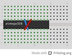
For a very quick setup all I do is connect VCC & AVCC to a power supply (3.3V or 5V) and the 2 GND pins to Ground. That’s it. It’s enough to get the chip going as long as it’s setup to use the internal oscillator.

basic_arduino_bb

If the chip arrives with a Uno Bootloader installed or even basic factory settings I prefer to change the settings to suit my needs. For this the fuses need to be set appropriately. The best resource I’ve found to determine the fuses is this link.

My preferred setup is to run the chip at 8MHz using it’s internal oscillator, no bootloader and brown-out detection at 2.7V. This gives me a setting of:

low_fuses = 0xE2
high_fuses = 0xDF
extended_fuses = 0x05

With this information I created my own Arduino board setting that I save in boards.txt under Arduino/hardware/breadboard/ folder.

atmega328abb.name=ATmega328 @ 8MHz – no bootloader

atmega328abb.upload.protocol=stk500
atmega328abb.upload.maximum_size=32256
atmega328abb.upload.speed=57600

atmega328abb.bootloader.low_fuses=0xE2
atmega328abb.bootloader.high_fuses=0xDF
atmega328abb.bootloader.extended_fuses=0x05
atmega328abb.bootloader.path=empty
atmega328abb.bootloader.file=empty
atmega328abb.bootloader.unlock_bits=0x3F
atmega328abb.bootloader.lock_bits=0x0F

atmega328abb.build.mcu=atmega328p
atmega328abb.build.f_cpu=8000000L
atmega328abb.build.core=arduino:arduino
atmega328abb.build.variant=arduino:standard

With this in place when I restart Arduino, I can see an additional entry under Boards.

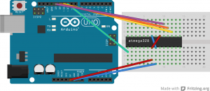
To burn the fuses to the chip I first load the ArduinoISP sketch on to an Uno (remember to choose Board = Arduino Uno when loading the ArduinoISP sketch). Then I hookup Uno pin 10 to Reset (PC6) on the chip, pin 11 to pin 11 (PB3/MOSI), pin 12 to pin 12 (PB4/MISO) and pin 13 to pin 13 (PB5/SCK). Note – 10, 11, 12 & 13 pins are used to allow communication via the SPI protocol.

arduino_programmer

Then I choose the Board (ATmega328 @ 8MHz – no bootloader) and then: Tools -> Burn Bootloader helps set the fuses. Note: Since the boot loader.file is specified as empty, the Arduino IDE will display an error. This is OK and the fuses have been reset.

If the chip came with an Arduino UNO bootloader it probably means the fuses are configured to expect an external 16MHz oscillator. In this case we need to add a crystal between XTAL1 & XTAL2 with 22pf bypass capacitors grounding both XTAL1 & XTAL2 pins. This is needed so that the chip can start up to receive the fuse set commands. Once the fuses have been set to use the internal oscillator, the crystal is no longer required.

To test everything went well, load up the blink sketch and upload it to the chip via “Upload Using Programmer”. Hopefully everything uploaded successfully and to see it in action hookup an LED to pin 13 via an appropriate resistor.

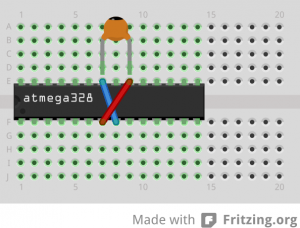
Finally when using the chip in a circuit I take the precaution to add a 0.1 uF bypass capacitor between VCC and GND. I also make sure I have a reservoir capacitor (say 47 uF) at the power supply to ensure a steady voltage.

basic_arduino_with_cap_bb

With just this setup I’ve been able to make very good use of these chips and have them run very reliably.